RETICLES
OPTICAL SIGHT
USER MANUAL FOR RETICLES.html RETICLES.html is a self-contained form that can run locally in a browser. It loads a reticle image and a BC001-BC004 ballistic report, converts point of impact (POI) into MIL or MOA angular units, and plots aiming points directly on the reticle image. The result is a ballistic table, a complete set of system parameters and an A4 PDF printout.
The image, report and configuration remain on the user's computer - the form sends no data to the network.
REQUIREMENTS AND STARTUP
- The form works in mobile browsers and on desktop computers.
- It can be run online or offline, locally on the computer.
CONTENTS
1 Title page, requirements and startup p. 1 2 Screen layout - form map (Fig. 1) p. 2 3 First start - sequence of actions p. 3 4 I/O files - loading, saving and work session p. 4 5 Sight and magnification - FFP / SFP p. 5 6 Scale calibration (Fig. 2) p. 6 7 Center adjustment - SET POI (Fig. 3) p. 7 8 Reticle screen (Fig. 4) p. 8 9 Distance, distance markers, turret (Fig. 5) p. 9 10 Wind, shooting angle and CLICK UP/DOWN turret setting p. 10 11 Ballistic table, point selection and +/-dV1 module p. 11 12 PDF printing p. 12 13 Parameter descriptions - glossary p. 13 14 Form elements - index p. 14 15 Form messages and troubleshooting p. 15
DATA FLOW
INPUT RETICLES.html OUTPUT Reticle image: PNG / JPG / SVG Scale calibration Ballistic table
CFG file (optional) CLICK turret settings A4 PDF printout · CFG file G1 / G7 / GA / GS drag-model tables are integrated into the form.
2 · SCREEN LAYOUT
The form is divided into two columns. The left column contains all control fields; the right one shows the reticle preview and the results table. On a narrow screen the columns are arranged one below the other. This screenshot shows the Polish interface; the English name of every element is given in the index on page 14.
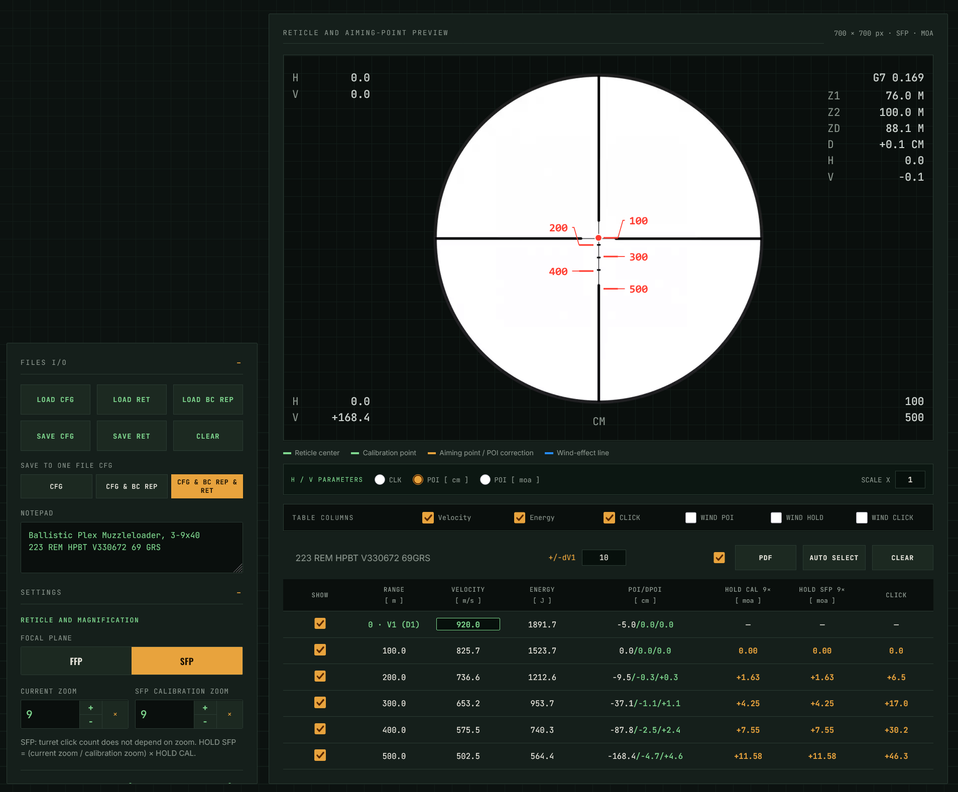
- I/O FILES - loading and saving the graphic, report and configuration.
- SAVE TO ONE FILE CFG - range of data saved in one CFG file.
- NOTEPAD - your own description stored in the CFG file.
- SIGHT AND MAGNIFICATION - FFP/SFP reticle focal plane and zoom.
- SCALE CALIBRATION - links image pixels to MIL or MOA.
- CENTER ADJUSTMENT - additional reference point (SET POI).
- DISTANCE - distance range from the report or custom (FROM / TO / STEP).
- MARKER SIZE - size of labels plotted on the graphic.
- TURRET - ELEVATION - click value and sight-geometry parameters.
- WIND - wind speed and angle.
- CLICK UP/DOWN - current turret setting and ZERO button.
- RETICLE AND AIMING-POINT PREVIEW - main working area.
- LEGEND - colors of markers on the reticle graphic.
- H / V PARAMETERS and SCALE X - readout unit and on-screen zoom.
- TABLE COLUMNS - enable or disable result columns.
- +/-dV1, INTEGRATED PRINT, PDF, AUTO SELECT, CLEAR.
- BALLISTIC TABLE - results and selection of points plotted on the reticle.
3 · FIRST START
On the first start, configure the form from an empty state. The sequence below prepares the reticle, ballistic report and aiming points.
- START THE FORM - open RETICLES.html in a browser, online or locally.
- LOAD THE RETICLE - use LOAD RET and select a PNG, JPG or SVG image. After loading, the image appears in the preview area.
- LOAD THE BALLISTIC REPORT - use LOAD BC REP and select a report created by BC001-BC004. The report provides trajectory data from which the form calculates POI, HOLD and CLICK.
- SET SIGHT TYPE AND ZOOM - select FFP or SFP. For SFP, also enter the calibration zoom; the current zoom defines the magnification used to display the reticle.
- CALIBRATE THE SCALE - indicate the reticle center and a second point at a known angular distance. Without calibration, points will not be plotted on the graphic.
- ENTER SIGHT PARAMETERS - one-click value, sight axis height, mount cant, Shooting Angle and turret-to-muzzle distance.
- SET WIND AND DISTANCE RANGE - if wind is to be included, enter its speed and angle. Take the distance range from the report or define it manually (FROM, TO, STEP).
- SELECT POINTS - use AUTO SELECT so the form selects points for the table and reticle, or select the desired rows manually in the SHOW column.
- SAVE THE CONFIGURATION - SAVE CFG. On later starts, LOAD CFG is enough. In SAVE TO ONE FILE CFG, choose whether the file contains only the configuration, configuration with BC report, or also the reticle image.
- PDF PRINT - the PDF button opens printing. A selected check box next to the button chooses the full integrated printout; cleared - only the reticle on an A4 sheet.
SHORT WORKFLOW
Calibration is performed on the vertical axis only. SET CENTER defines the reticle center and at the same time the vertical calibration axis; the second point is always positioned on the same vertical axis as the center.
4 · I/O FILES
The I/O FILES section loads input data and saves work results. The status of each operation is shown by a message below the buttons.
BUTTONS
LOAD CFG
Loads the form configuration file (.txt). Restores settings, calibration and point selection and, depending on the file contents, also the BC report and reticle image.
LOAD RET
Loads the reticle image. Supported formats: PNG, JPG and SVG. The image remains local in the browser.
LOAD BC REP
Loads a ballistic report created by BC001-BC004 (.txt).
SAVE CFG
Saves the current form configuration to a text file.
SAVE RET
Saves the reticle image with plotted points as a PNG image.
CLEAR
Clears the form and restores the initial state. It also deletes the stored work session.
SAVE TO ONE FILE CFG - SAVE SCOPE
CFG
Form configuration only.
CFG & BC REP
Configuration together with the ballistic report contents.
CFG & BC REP & RET
Configuration, report and reticle image embedded in the file. One file restores the complete working setup.
NOTEPAD
Text field for your own configuration description - firearm, ammunition, zeroing date. The notepad content is saved and loaded together with the CFG file.
WORK SESSION
When running from a local disk or on touch devices, the form stores the current state in browser storage and restores it when reopened. The stored session does not replace the CFG file - always use SAVE CFG to transfer a configuration between computers.
Saved file names contain a time stamp, for example RETICLES_CFG_20260907_143512.txt and RETICLE_20260907_143512.png. The browser may also ask you to select a save location.
5 · SIGHT AND MAGNIFICATION
This section defines the sight type and magnifications used in calculations and reticle display.
RETICLE FOCAL PLANE
FFP
First focal plane reticle. The angular scale remains correct at every magnification - the HOLD correction does not depend on zoom.
SFP
Second focal plane reticle. The number of turret clicks does not depend on zoom, but the correction value plotted on the reticle depends on the current magnification.
ZOOM
CURRENT ZOOM
Magnification currently set on the sight. Used for calculating the HOLD SFP column and for displaying the preview.
SFP CALIBRATION ZOOM
Reference magnification for an SFP reticle - the zoom at which the reticle scale matches its nominal value. The field is active only after SFP is selected.
HOLD CONVERSION FOR SFP
HOLD SFP = ( current zoom / calibration zoom ) x HOLD CAL For FFP the factor equals 1 - the HOLD SFP column is not displayed. In SFP mode, the results table shows two correction columns: HOLD CAL - the value at calibration zoom, and HOLD SFP - the value converted for the current magnification. Both column headers include their corresponding zoom values, so the printout remains unambiguous.
Changing the current zoom does not affect the CLICK column. The turret setting is an angular quantity and remains independent of magnification in both FFP and SFP.
6 · SCALE CALIBRATION
Calibration links the angular values of the sight reticle (MOA or MIL) to the pixel distance measured on the loaded graphic. From this, the form determines the pixel-to-angle conversion and can correctly plot points and POI corrections on the reticle.
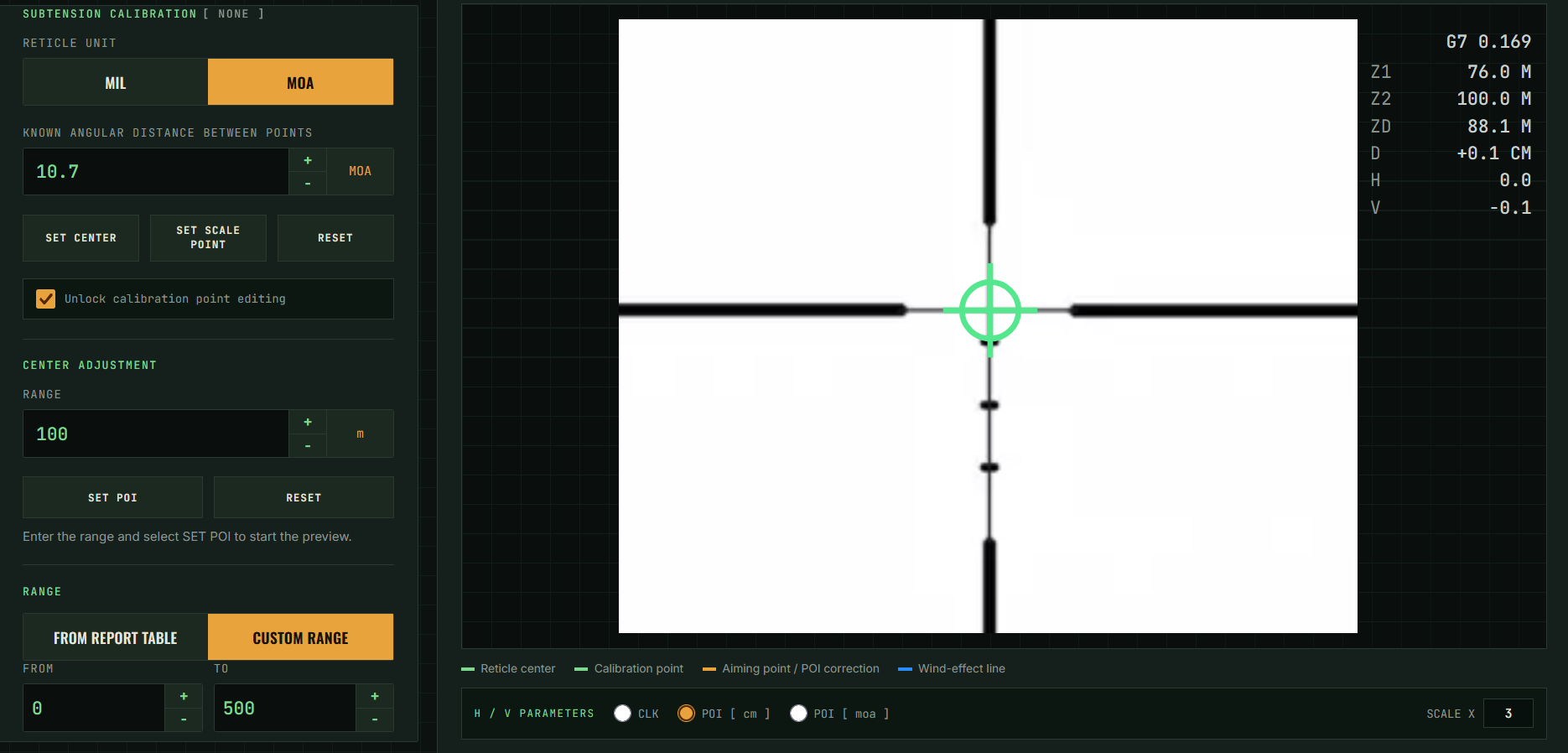
- Select the reticle unit and enter the known angular distance between two grid points.
- The “Lock calibration points position” option allows calibration points to remain permanently visible.
- The “SET CENTER” button is used to indicate the center of the reticle. This point defines the vertical calibration axis.
- The “SET SCALE POINT” button is used to indicate the second point. Calibration is performed only on the vertical axis, and the second point is placed on the same vertical axis as the center.
- To remove the points and perform calibration again, use RESET. Reticle calibration aims to link the reticle grid parameters (MOA or MIL) with the graphic pixel values.
CONVERSIONS
1 MOA 1/60 degree = pi/(180·60) rad ≈ 0.290888 MIL.
1 MIL 0.001 rad = 180/(pi·1000) degree ≈ 3.43775 MOA.
Linear displacement L = D · tan(n · MOA), where D is the distance. For MIL: L = D · tan(n/1000), and for small angles approximately L = D·n/1000. D and L must be given in the same units of length.
7 · CENTER ADJUSTMENT - SET POI
This function lets you indicate an additional reference point on the graphic as a blue cross. After it is set, the green H/V cursor parameters are measured from that point rather than from the reticle center. This makes it easier to read the correction between the actual point of impact and the selected aiming point.
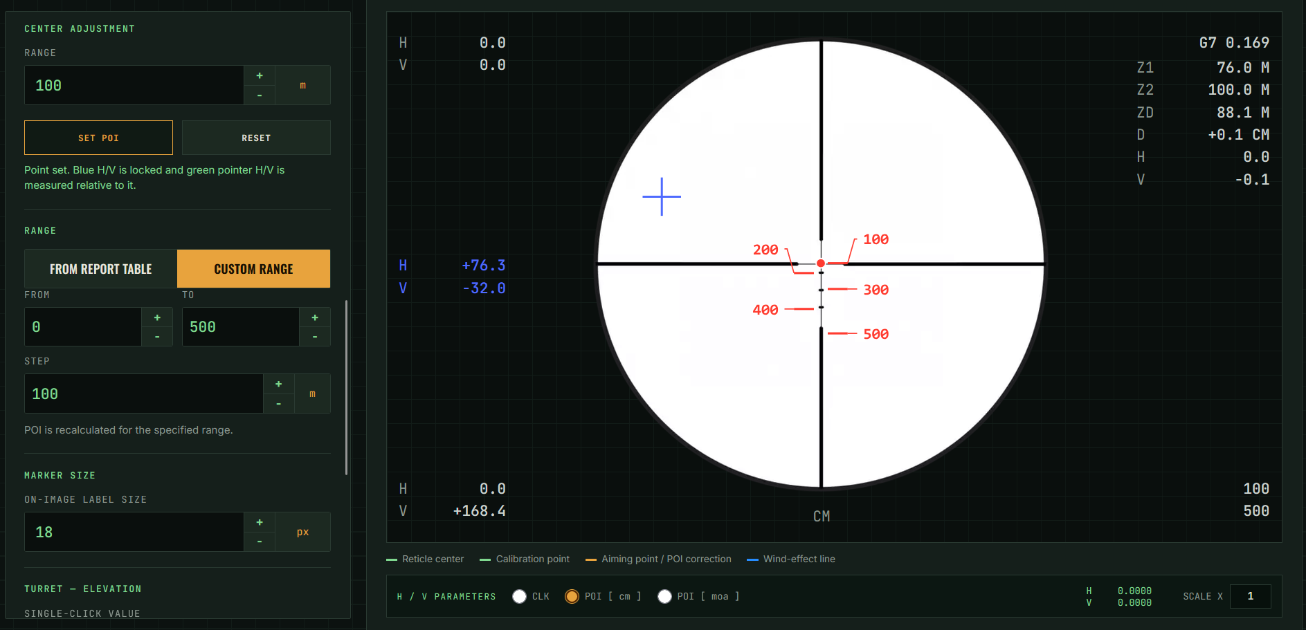
- CENTER DISTANCE — Distance for which the displayed H/V parameters change for the mouse cursor position.
- SET ZERO — Enables setting an additional reference point in the form of a blue crosshair.
- RESET — Removes the blue crosshairs from the grid screen.
- BLUE CROSSHAIR — Additional reference point. When set, its position is displayed and the H/V parameters in the field are zeroed.
- BLUE H/V COORDINATES — Position values of the set reference point.
- H/V PARAMETERS — Position of the mouse cursor H/V. In case the blue crosshair is set, these are zeroed.
- SCALE X — Increases the grid size from 1 to 5. Mouse clicks on the grid screen move the blue crosshair as long as the cursor is over the graph. After leaving the graph, the crosshair position is locked. In mobile applications, mouse-related functions may be inactive.
SEQUENCE OF ACTIONS
- Load the graphic and calibrate the scale - the function will not work without calibration.
- In CENTER DISTANCE, enter the distance for which the H/V parameters are to be calculated.
- Press SET POI, then click the selected point on the reticle graphic.
- Further clicks move the cross while the pointer remains over the graphic. After leaving the graphic the position is locked.
- RESET removes the cross and restores measurement from the reticle center.
8 · RETICLE SCREEN
The preview shows the loaded reticle graphic with plotted distance markers, the wind-effect line and calibration points. Information cards on both sides of the preview show trajectory parameters and the outermost markers visible on the reticle.
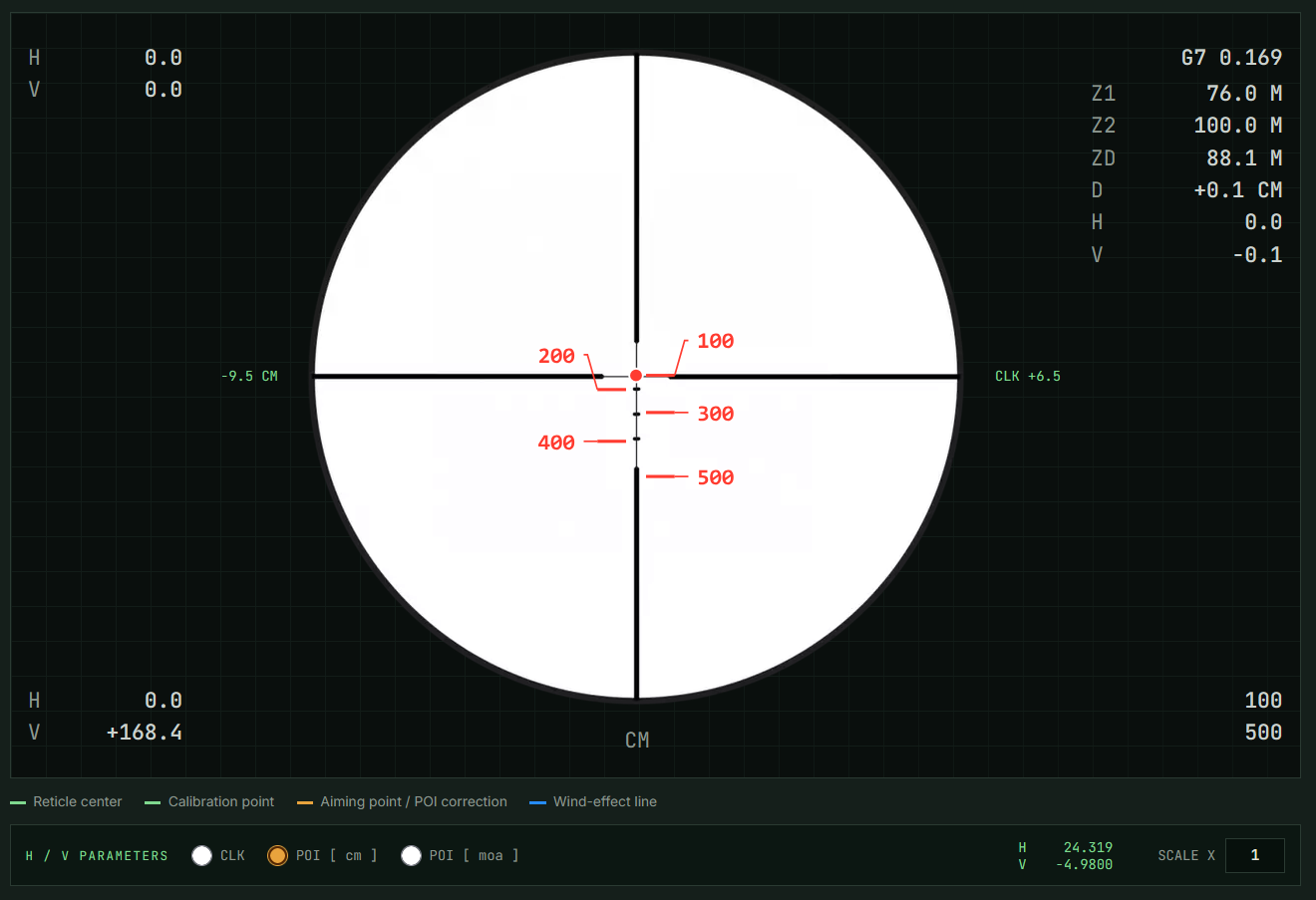
- Information about image resolution, focal-plane type, and subtension unit.
- Display of the H and V parameters of the highest distance marker on the reticle. In the example: 100 m.
- Main reticle preview area with the reticle and plotted points.
- G model, Z1 closer zero, Z2 farther zero, ZD distance for the trajectory apex, D trajectory rise relative to zero.
- Distance-marker labels from the ballistic table.
- Position of the distance marker on the V (vertical) axis in POI units, shown when hovering the mouse cursor. Example: POI -9.5 cm for 200 m.
- Position of the distance marker on the V (vertical) axis in CLICK units, shown when hovering the mouse cursor. Example: CLK +6.5 for 200 m.
- Display of the H and V parameters of the lowest distance marker on the reticle. In the example: 500 m.
- Value of the lowest and highest distance marker on the reticle.
- Selection of CLK or POI parameters.
- Cursor coordinates on the reticle in MOA / MIL, POI or CLICK (CLK).
- Reticle magnification from 1 to 5. It can be used for subtension calibration.
CURSOR AND DATA DISPLAY
Hovering the pointer over a marker label shows POI in centimeters at the sides of the graphic and the corresponding CLK click count. H/V PARAMETERS switches the cursor-coordinate readout unit: CLK, POI [cm] or POI [moa] / POI [mil]. SCALE X enlarges only the on-screen preview in the range 1 to 5 and does not affect results.
9 · DISTANCE, DISTANCE MARKERS, TURRET
This group of fields determines which points go to the table and graphic and how they are converted into turret settings.
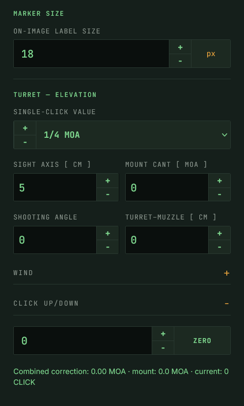
- RANGE SELECTION — Range selection from the report table or according to custom parameters.
- MARKER SIZE — Label size on the graphic, expressed in px.
- VALUE PER ONE CLICK — Value of a single click of the turret adjustment. Example: 1/4 MOA.
- SCOPE PARAMETERS — Scope axis, mount cant, Shooting Angle and Turret-muzzle. These parameters affect geometry and adjustment calculations. Turret-muzzle: distance between the center of the UP/DOWN turret and the muzzle. Used exclusively for calculating the adjustment range. Does not affect the ballistic table.
- PDF CHECKBOX — Selected: the PDF printout includes the report and charts. Not selected: only the reticle grid is printed in A4 format.
- PDF — Starts PDF printing.
FIELD DETAILS
DISTANCE
FROM REPORT TABLE - non-zero distances stored in the report are used. CUSTOM RANGE - POI is calculated for the FROM / TO / STEP range.
MARKER SIZE
Size of labels plotted on the graphic, in pixels. Range 12-36; default value 18.
ONE-CLICK VALUE
Value of one turret adjustment step: mm/100 m or 1/8, 1/4, 1/2 or 1 MOA.
SIGHT PARAMETERS
Sight axis height, mount cant, Shooting Angle and turret-to-muzzle distance. They affect geometry and adjustment-range calculations. Turret-to-muzzle is used only to calculate the adjustment range and does not change the ballistic table.
10 · WIND, SHOOTING ANGLE AND TURRET SETTING
WIND
WIND SPEED
A value in m/s or mph — the unit is chosen from the list next to the field. Changing the unit converts the entered value automatically.
WIND ANGLE
Wind is accounted for in the WIND POI, WIND HOLD and WIND CLICK columns, and a blue wind-effect line joining the points of impact is drawn on the reticle image.
SHOOTING ANGLE
The angle of the bore axis relative to horizontal, in the range from −89° to +89°. It is taken into account in the trajectory calculations.
CLICK UP/DOWN
The field holds the current turret displacement from the zero setting, expressed in clicks. Entering a value moves the aiming point on the image and changes the POI column.
- The ZERO button adopts the current setting as the new zero and resets the click counter.
- Below the field the combined correction is shown: the UP or DOWN direction, the value in MIL and MOA, the direction of the aiming-point shift, the mount cant and the click count.
- The mount cant given in MOA is subtracted from the turret correction — this shows the extension of the adjustment range obtained with a canted mount or rail.
CALCULATED ADJUSTMENT RANGES
Once the turret–muzzle distance is entered, the form derives additional parameters, visible in the parameter section and on the printout:
CLKZ1
Adjustment distance from the turret center to the position corresponding to the current Z1, expressed in CLICK.
dCLKZ1 Extension of the adjustment range in CLICK obtained by using a canted mount or rail.
CLKZD
Adjustment distance from the turret center position to the position corresponding to ZD, expressed in CLICK.
The turret–muzzle distance takes values from 0 to 500 cm and serves only to compute the adjustment range. It does not affect the ballistic table.
11 · BALLISTIC TABLE AND POINT SELECTION
The table contains results for successive distances. DISTANCE, POI, HOLD and HOLD SFP are always visible; the remaining ones are switched on in the TABLE COLUMNS section. The HOLD SFP column appears only when an SFP scope is selected.
COLUMNS
DISTANCE
Distance for which the row was calculated.
VELOCITY / ENERGY
Projectile velocity and energy at the given range.
POI
Point-of-impact position relative to the line of sight.
HOLD / HOLD SFP
Correction applied on the reticle without changing the turret setting.
CLICK
The correction expressed in turret adjustment clicks.
WIND POI / WIND HOLD / WIND CLICK
Lateral point-of-impact shift caused by wind and the corresponding corrections.
SELECTING THE POINTS PLACED ON THE RETICLE
- SHOW column — ticks a single row to be placed on the image.
- AUTO SELECT — the form chooses the points so that their labels do not overlap.
- CLEAR — removes all the ticks.
- Below the table the number of selected and actually visible points is displayed.
If there is no free position away from the reticle lines for a ticked point, the row is dimmed and the form reports that another point must be hidden or the label size reduced.
THE V1 ROW AND THE +/−DV1 MODULE
The first row of the table, marked 0 · V1 (D1), holds the initial projectile velocity. The check box in that row unlocks editing of the V1 velocity and the +/−dV1 module.
- Once unlocked, the +/−dV1 field takes the velocity deviation from V1.
- The POI column changes into POI/dPOI and shows results for the range from V1−dV1 to V1+dV1.
- The maximum permitted dV1 is limited by the velocity at the longest range in the table.
12 · PDF PRINT
The PDF button opens the browser print dialog. The contents of the printout are decided by the check box placed directly to the left of the button.
PRINT MODES
CHECK BOX TICKED
Integrated, black-and-white printout. It contains the ballistic table, the parameters and specification of the system, the calculated adjustment ranges, the reticle image, the velocity, energy, POI and CLICK charts, and the parameter glossary.
CHECK BOX CLEARED
Only the centred, enlarged reticle is printed on an A4 sheet, with red point markers. All remaining elements stay black and white.
PRINT DIALOG SETTINGS
- Disable „Headers and footers” to remove the page title and the URL from the sheet.
- The integrated printout is prepared in landscape orientation — keep the setting proposed by the form.
- Enable background graphics printing if the browser omits the table rules.
- To obtain a file instead of a printout, choose the „Save as PDF” printer.
CONTENTS OF THE INTEGRATED PRINTOUT
Page 1 The ballistic table together with the parameter and specification block, the reticle preview and the print date.
Page 2 Charts: velocity/range, energy/range, POI/range and CLICK/range, with the Z1, Z2 and ZD markers.
Page 3 The parameter glossary.
If no reticle image has been loaded, the printout omits the reticle preview and the parameter glossary follows directly after the table.
13 · PARAMETER DESCRIPTIONS
Definitions of the quantities used in the form, in the results table and on the printout.
Sight axis Distance between the sight optical axis and the bore axis.
Turret–muzzle Distance between the center of the UP/DOWN turret and the muzzle. Used only to calculate the adjustment range. It does not affect the ballistic table.
Mount cant [MOA] Sight inclination introduced by a canted mount or rail.
Shooting Angle Angle of the bore axis relative to horizontal.
ZERO
Selected zero range used to determine the trajectory.
Z1
Nearer intersection of the trajectory with the line of sight.
Z2
Farther intersection of the trajectory with the line of sight.
D
Maximum trajectory height above the line of sight.
ZD
Range at which the maximum height D occurs.
CLKZ1
Adjustment distance from the turret center to the position corresponding to the current Z1, expressed in CLICK.
dCLKZ1 Extension of the adjustment range in CLICK obtained by using a canted mount or rail.
CLKZD
Adjustment distance from the turret center position to the position corresponding to ZD, expressed in CLICK.
CLICK UP/DOWN
Current turret displacement from the zero setting, expressed in CLICK.
CLICK
Value of one turret adjustment step.
POI
Point-of-impact position relative to the line of sight.
HOLD
Correction applied on the reticle without changing the turret setting.
HOLD SFP
Reticle correction converted to the current magnification of an SFP scope.
WIND POI
Lateral point-of-impact shift caused by wind.
WIND HOLD
Wind correction applied on the reticle.
WIND CLICK
Wind correction expressed in CLICK.
V1
Initial projectile velocity.
dV1 Velocity deviation from V1.
BC
Projectile ballistic coefficient.
Model G1 / G7 / GA / GS Aerodynamic drag model used in the calculations.
14 · FORM ELEMENTS — INDEX
Every field and button of the form, in the order in which it appears on screen. The Polish label shown in the screenshots of this manual is given in brackets.
LOAD CFG
Loads a form configuration file.
LOAD RET
Loads the reticle image (PNG, JPG or SVG).
LOAD BC REP
Loads a BC001–BC004 ballistic report.
SAVE CFG
Saves the current form configuration.
SAVE RET
Saves the reticle image with the placed points.
CLEAR
Clears the form and restores the initial state.
SAVE TO ONE FILE CFG
Selects the scope of data written to a single CFG file.
CFG / CFG & BC REP / CFG & BC REP & RET
Whether to save the configuration only, the configuration with the BC report, or the configuration with the BC report and the RET image.
NOTEPAD [ Notatnik ] Custom description stored and restored in the CFG file.
FOCAL PLANE [ Płaszczyzna krzyża ] Choice of FFP or SFP.
CURRENT ZOOM [ Bieżący zoom ] Magnification used for calculations and preview.
SFP CALIBRATION ZOOM [ Zoom kalibracyjny SFP ] Reference magnification for the reticle in SFP scopes.
RETICLE UNIT [ Jednostka podziałki ] Angular unit of the calibration: MIL or MOA.
KNOWN ANGULAR DISTANCE [ Znana odległość kątowa ] Angular value used to calibrate the reticle.
SET CENTER [ Ustaw środek ] Sets the reticle center during calibration.
SET SCALE POINT [ Ustaw punkt skali ] Sets the second calibration point at a known angular distance.
RESET
Resets the current calibration or the indicated section.
UNLOCK CALIBRATION POINT EDITING [ Odblokuj ustawianie punktów kalibracji ] Allows the calibration points to be set manually.
CENTER ADJUSTMENT RANGE [ Dystans ] Range used by the SET POI function.
SET POI [ Ustaw POI ] Activates setting of the point of impact on the reticle.
RANGE / FROM / TO / STEP [ Dystans / Od / Do / Krok ] Range of distances used to generate points from the table or for a custom range.
ON-IMAGE LABEL SIZE [ Wielkość opisów na grafice ] Size of the point labels and captions in the preview.
SINGLE-CLICK VALUE [ Wartość jednego kliku ] Value of one turret adjustment step.
SIGHT AXIS [ CM ] [ Oś celownika ] Height of the sight axis above the bore.
MOUNT CANT [ MOA ] [ Skos montażu ] Inclination introduced by the mount or rail.
SHOOTING ANGLE
Angle of the bore axis relative to horizontal.
TURRET–MUZZLE [ CM ] [ Wieża–wylot ] Distance from the center of the UP/DOWN turret to the muzzle.
WIND
Section holding the crosswind parameters.
WIND SPEED / WIND ANGLE [ Prędkość wiatru / Kąt wiatru ] Wind parameters used to compute the lateral correction.
CLICK UP/DOWN
Current turret setting and the field that zeroes it.
RETICLE AND AIMING-POINT PREVIEW [ Podgląd krzyża i punktów celowania ] Large preview area with points, labels and the wind effect.
H / V PARAMETERS [ Parametry H / V ] Presentation of the coordinates: CLK, POI [cm] or POI [mil].
SCALE X [ Skala X ] On-screen magnification of the image, from 1 to 5.
TABLE COLUMNS [ Kolumny tabeli ] Check boxes switching the visible table columns on and off.
+/−dV1 Field for the velocity deviation from V1.
INTEGRATED PRINT [ Druk zintegrowany ] Check box selecting the full printout or the reticle alone on A4.
Starts the printout of the report and the reticle.
AUTO SELECT [ Auto wybór ] Automatically selects and shows points in the table and on the reticle.
CLEAR [ Wyczyść ] Clears the point selection in the results section.
BALLISTIC TABLE [ Tabela balistyczna ] Results for successive ranges: POI, HOLD, CLICK and the wind corrections.
15 · MESSAGES AND TROUBLESHOOTING
The form reports its working state with messages displayed below the relevant sections. The messages that require action from the user are listed below.
The report does not contain enough data to determine BC. The BC report is incomplete. Generate it again in BC001–BC004.
V1, sight height or zero range is missing. Complete the missing parameters in the report or in the form fields.
No reticle image loaded. Use the LOAD RET button and select an image in PNG, JPG or SVG format.
Load a reticle image first. Calibration and center adjustment require a loaded image.
Set the center first with the SET CENTER button. The scale point can be marked only after the reticle center has been set.
Calibration point editing is locked. Tick the „Unlock calibration point editing” option.
The calibration points are too close together. Mark the second point farther from the center — the vertical distance must be clear.
Enter a positive subtension value. The known angular distance field must hold a value greater than zero.
Calibrate the reticle center and subtension first. The SET POI function requires a completed calibration.
Enter a positive single-click value. Complete the SINGLE-CLICK VALUE field in the TURRET — ELEVATION section.
No valid ranges. Check the FROM, TO and STEP fields — TO must not be smaller than FROM, and STEP must be positive.
Load a report and calibrate the image. The table stays empty until a report is loaded and the calibration is done.
No free position away from reticle lines. The point label does not fit outside the reticle lines. Hide another point or reduce the on-image label size.
The configuration file is invalid or damaged. The CFG file does not come from this form or has been damaged. Load another file.
If the table stays empty despite a loaded report, check the calibration status first — it should show a value in the form [ 94.5 px = 10.7 MOA ], not [ NONE ].
Content source: RETICLES_EN.txt